Diy Arduino Gimbal
A 3D printed Do-It-Yourself (DIY) gimbal -- fitted with 3 FS90 Micro servo motors -- is controlled using an MPU6050 inertial measurement unit (IMU) sensor to keep the 3D printed platform stable during rotation in any axis. The servo motors and the IMU sensor are connected to the Arduino Nano microcontroller.
Hardware
Components
The following components (and tools) were used in this project:
-
3D printed gimbal parts
-
Arduino Nano (and usb cable)
-
MPU6050 board
-
3 x FS90 Micro servo motors
-
LM2596 Buck Regulator
-
9V battery and connector
-
2.54 mm female and male headers
-
Loose cables to solder on female/male headers
-
Veroboard to solder on female headers (for the arduino nano and MPU6050) and male headers for the servo cables
-
On/Off switch
-
Soldering iron
-
Screwdriver set
-
Double sided tape
-
Duck tape
Project Wiring
The diagram below shows how the electronic components of the gimbal were connected.
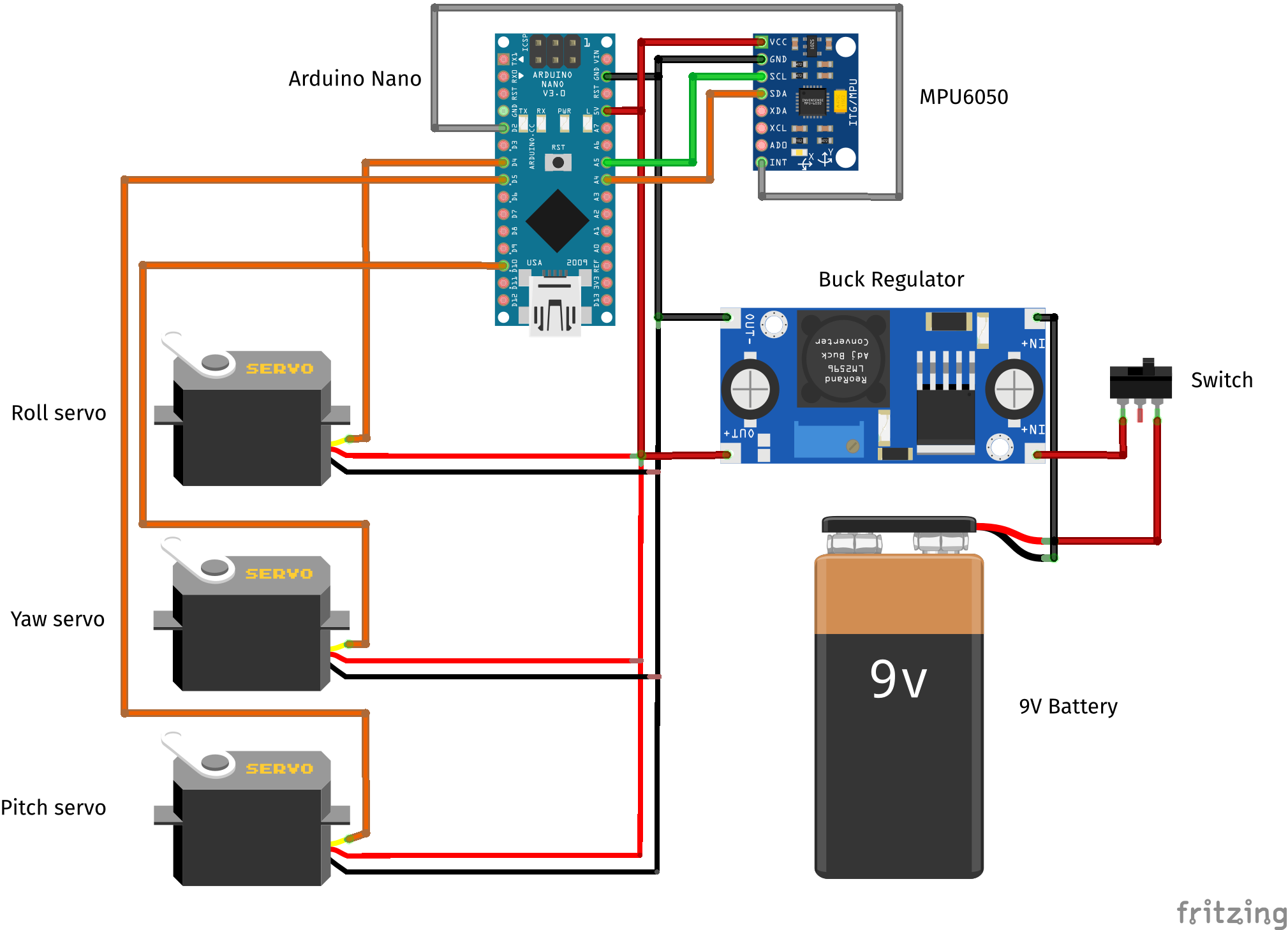
The 9V battery provides the power for the project and is connected to a buck/voltage regulator which steps down the voltage to 5V for the Arduino Nano. A switch is connected inline with the regulator and battery to open or close the circuit.
The MPU6050 board pins were connected to the Arduino Nano pins as follows:
| MPU6050 board | Arduino Nano board |
|---|---|
| VCC | 5V |
| GND | GND |
| SCL | A5 |
| SDA | A4 |
| INT | D2 |
The pair of analog pins, A4 and A5, on the Nano are usually used for I2C communications according to the board pinout. Hence, pins A4 and A5 are connected to SDA and SCL on the MPU6050 board respectively. The external interrupt pin of the MPU6050 is connected to the D2 digital pin.
The signal cable of the servo motors are connected to the Nano as follows:
| Servo | Arduino Nano board |
|---|---|
| Roll | D4 |
| Pitch | D5 |
| Yaw | D10 |
Assembly
The physical parts of the gimbal: the platform, servo housings and the main body were 3D printed. The STL files used to 3D print the project parts can be found here from Make It Smart and are also provided in the project repository.

The Nano and MPU6050 boards were attached to a breadboard using female headers. The servo motors were connected to the Nano via male headers soldered onto the breadboard (to the left of the Nano in the image below). The signal, ground and vcc connections were soldered underneath the breadboard to the corresponding pins on the Nano.
An extra column of headers was attached for debugging power and ground connections.
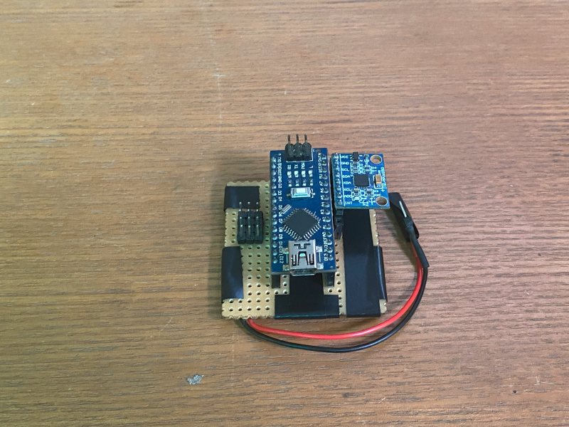
The black and red wires shown are connected to the ground and the voltage output from the buck regulator. The idea behind this connection and assembly is again attributed to Make It Smart. The servos are attached to the servo housings with screws, the double sided tape is used to attach the breadboard securely in the gimbal body and to insulate connections from possible short circuits.
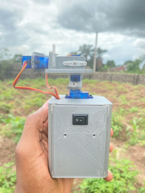
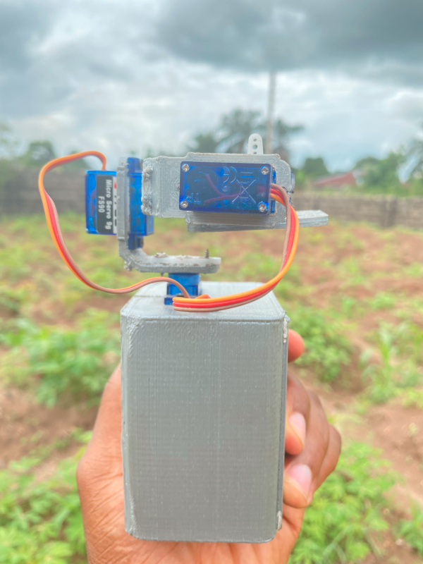
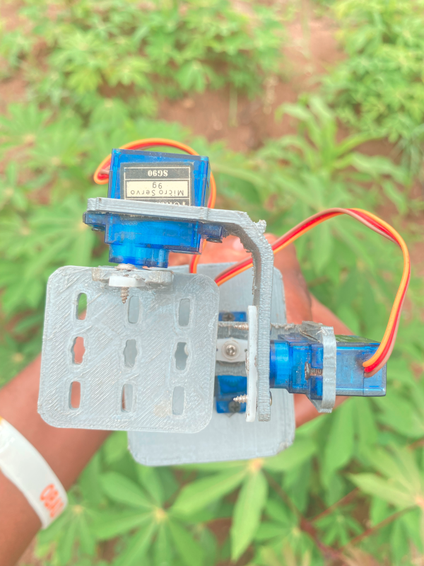
The fully assembled gimbal is shown in the pictures below.
Software and libraries
The Arduino IDE was used in programming this project. The i2cdevlib and MPU6050 libraries by Jeff Rowberg were the main libraries utilized in this project. These libraries can be installed by importing them into the Arduino IDE as explained in the README of the repository; this guide can also be instructional for the installation process.
MPU6050 board
The MPU6050 board, shown below, is a Micro Electro-Mechanical System (MEMS) which consists of a 3-axis gyroscope -- to measure angular velocity -- and a 3-axis accelerometer, to measure acceleration. The board is also called an Inertial Measurement Unit (IMU) which provides a 6-degree of freedom system for motion tracking and measures velocity, orientation, acceleration, displacement and other motion related parameters.
The pinout of the MPU6050 is shown below:
| Pin | Description |
|---|---|
| VCC | 3 - 5V |
| GND | Ground |
| SCL | Serial Clock |
| SDA | Serial Data |
| XDA | Auxiliary Serial Data |
| XCL | Auxiliary Serial Clock |
| ADD | I2C address select |
| INT | Interrupt |
Other features of the board are as follows:
- In-built Digital Motion Processor (DMP) provides high computational power for complex calculations
- In-built 16-bit ADC provides high accuracy
- Uses an Inter-Integrated Circuit (I2C) module to interface with devices like an Arduino using the I2C protocol
- 3-axis gyroscope (angular rate sensor) with a sensitivity up to 131 LSBs/dps and a full-scale range of ±250, ±500, ±1000, and ±2000dps
- 3-axis accelerometer with a programmable full scale range of ±2g, ±4g, ±8g and ±16g
- In-built temperature sensor
Additional features and specifications can be found in the MPU6050 datasheet.
The I2C protocol is used to interface the MPU6050 module with the Arduino Nano. Jeff Rowberg's library employs the Arduino Wire library used to enable communication between I2C devices.
Some applications of the MPU6050 board include the following:
- IMU Measurement
- Drones/quadcopters
- Robotic arm controls and
- Self balancing robots
As stated earlier, the MPU6050 board is employed to balance the gimbal platform, how this works will elaborated on in a subsequent subsection.
Three Dimensional (3D) Rotations
Before delving further into the project, it's essential to gain some understanding of the fundamentals of rotations in 3D space.
Firstly, the terms orientation and rotation have to be defined. Orientation can be defined as the current angular position of an object, while rotation is the operation or action that changes the object's orientation.
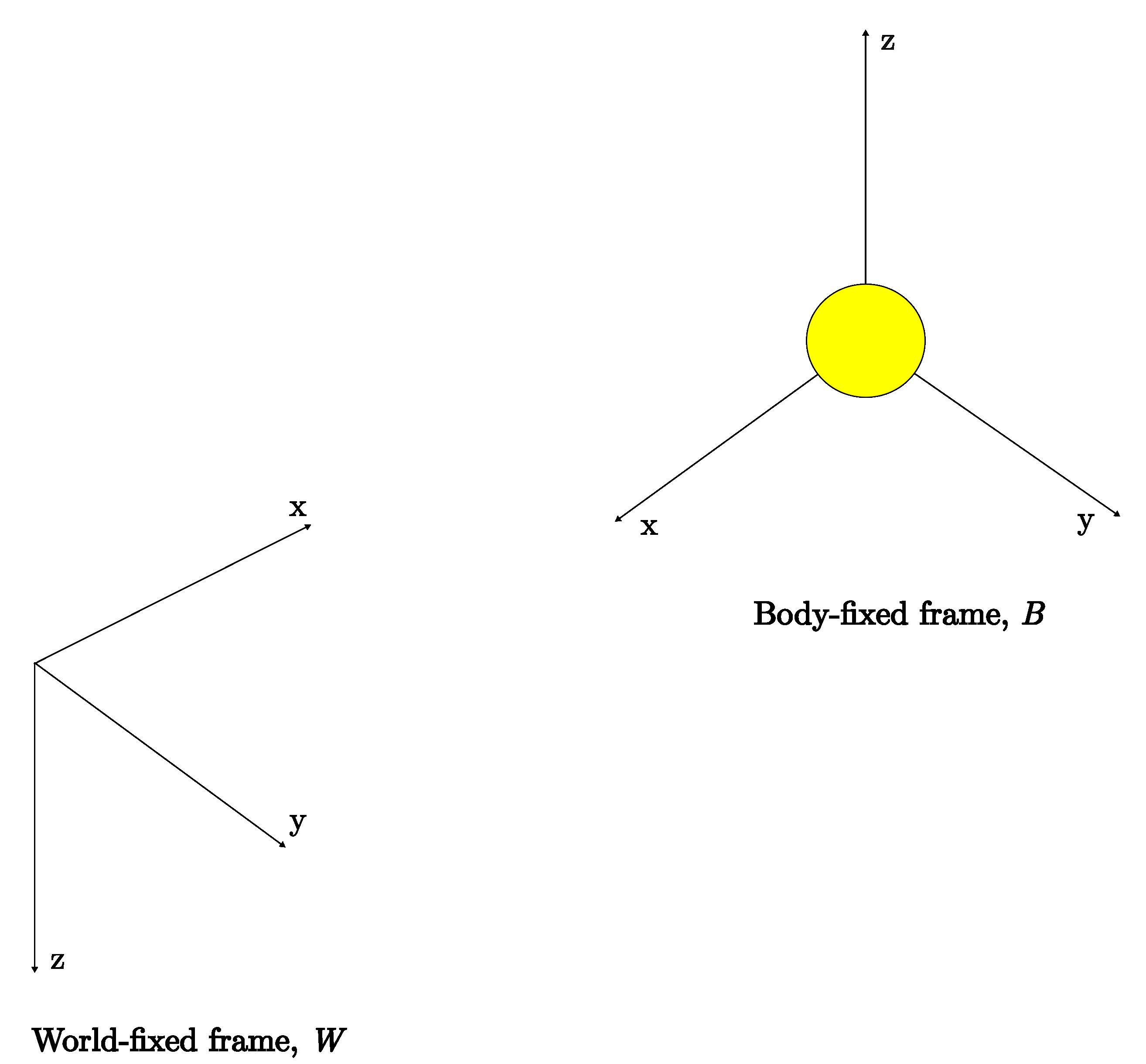
Typically, coordinate frames are used in representing 3D orientation and rotations of an object. This is necessary so that the object has a reference in the real world (in relation to itself) to locate itself, avoid obstacles and more. In a simplified instance, there is a coordinate frame on the object (consider the yellow ball in the figure below), usually known as the body-fixed frame, B, and a reference frame commonly known as the world/earth-fixed frame, W. With two coordinate frames, parameters that are measured or observed in the world-fixed frame can be related in the body-fixed frame and vice versa.
The common methods of representing 3D rotations are:
- Three-angle representation
- Axis angle and
- Quaternions
For brevity, only the three-angle representation and quaternions will be considered here.
Three-angle representation
As the name implies, in this method, the orientation and rotation of an object in 3D space is represented using three angles namely: 𝜃 (for rotation around the z-axis), 𝜙 (for rotation around the y-axis), and 𝜓 (for rotation around the x-axis). These angles are known as Euler angles with the direction of the axes determined by the right-hand rule convention.
Rotations using the three-angle representation method can be carried out in two ways:
- Euler rotation sequence or
- Cardan rotation sequence.
In the Euler rotation sequence, rotation occurs about two axes but no successive rotation about the same axis: XYX, YXY, YZY, ZYZ, XZX, and ZXZ.
However, in the Cardan rotation sequence, rotation occurs about all three axes: XYZ, XZY, YXZ, YZX, ZYX, ZXY. Sometimes Cardan rotation sequences are considered as a more specific case of Euler rotation sequences -- effectively categorizing all sequences as Euler rotation sequences. Another point to note is that the rotation sequences are non-commutative, meaning sequence XYZ ≠ ZYX.
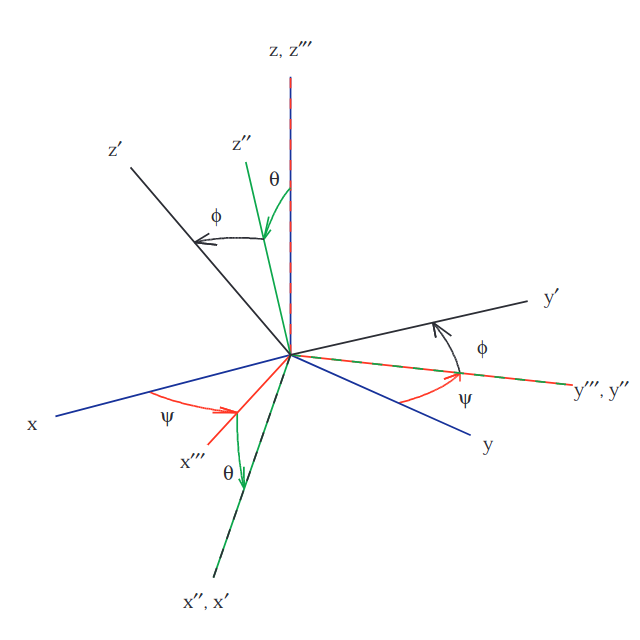
ZYX Cardan rotation sequence (from FRyDOM)
In the above rotation sequence, the first rotation of angle, 𝜓, is about the z-axis, the second rotation of angle, 𝜃, is about the y'''- axis with the final rotation of angle, 𝜙, about the x''-axis. This sequence is implemented with the use of rotation matrices. Each rotation in the sequence is expressed as a rotation matrix and the matrix multiplication of the three rotation matrices results in the new orientation, x'''y'''z'''.
Consider the following instance,

The rotation sequence is ZYX as shown by the matrix multiplication of the matrices Rz with angle 𝛼 (yaw), Ry, with angle 𝛽 (pitch), and Rx with angle 𝛾 (roll). R is the product of the rotation matrices.
The three-angle representation is a consequence of the Euler's rotation theorem which states:
Any two independent orthonormal coordinate frames can be a sequence of rotations(not more than three) about coordinate axes, where no two successive rotations may be about the same axis.
Representing 3D rotations in this format is natural and intuitive, however, this format runs into the problem of gimbal lock where one degree of freedom is lost because two of the three coordinate axes are parallely aligned at certain points. Considering a rotation sequence of ZYX, rotating the y-axis by ±90 degrees (or any multiples of 90) will cause the outer axes of the sequence, z-axis and x-axis, to be aligned and rotation about these axes will have the same effect; eseentially, rotations about these axes are indistinguisable. This problem can be viewed graphically and proven mathematically as well. Gimbal lock is avoided by making use of quaternions.
Quaternions
Quaternions are another way of representing 3D rotations and orientation and are a 4-dimensional extension of the complex numbers as shown:
s + v1i + v2j + v3k
where s, v1, v2, and v3 are real numbers and i, j and k are unit vectors. There are different notations for the real numbers depending on the application, programming language or literature in use. Some of these notations are as follows,
s = q0 = q1 = w
v1 = q1 = q2 = x
v2 = q2 = q3 = y
v3 = q3 = q4 = z
Quaternions are sometimes simplified as:
q = [s v]
Where s is the scalar part and v is the vector part.
To represent rotations and orientations in three dimensions, unit quaternions are used. They're of the form,
q = [s v] = [cos(𝜃/2) vsin(𝜃/2)]
Where v is a unit vector that defines an axis of rotation and 𝜃 is the amount of rotation about this axis. Unit quaternions have a magnitude have a magnitude of 1,
∥q∥ = 1
Recall from trigonometry that,
cos(𝜃)2 + sin(𝜃)2 = 1
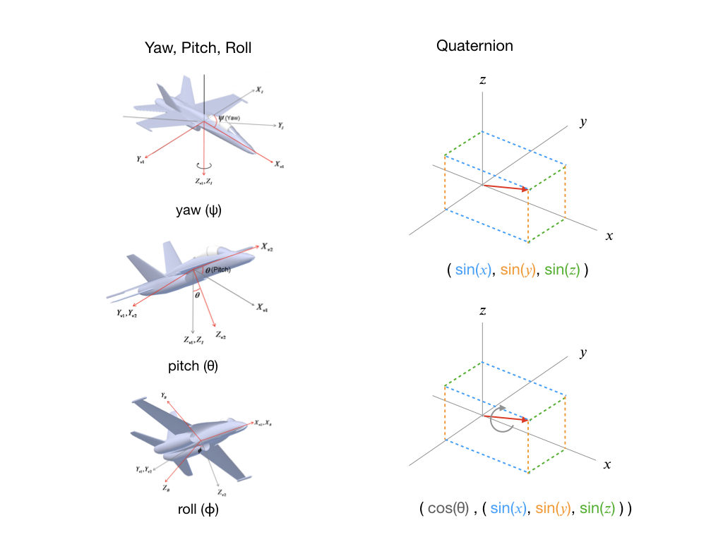
Unit quaternions can be represented visually as shown below courtesy of Martin White which is juxtaposed with the Yaw, Pitch and Roll angles. In the image, the red arrow is the unit vector given as sines and the grey arrow is the rotation about the vector.
Suppose there exists a point p in 3D space (x, y, z) to be rotated about a unit vector axis of rotation, v, with an angle, 𝜃. Rotation is carried about by the quaternion multiplication,
qpq-1
Where q-1 is the inverse of the unit quaternion q and p is expressed in quaternion format as [0, (x, y, z)]. This quaternion multiplication is also applicable to rotation between coordinate frames.
Quaternions can be complicated to understand compared to the more intuitive three-angle representation previously discussed and only the basics have been considered here but for more information on fundamentals of quaternions, derivations of quaternion properties and visual representation the references, here, here and here are great places to start.
Despite the relative steep learning curve, quaternions are simpler to compose, more numerically stable and more efficient than other methods of 3D representation. They're utilized in computer graphics, computer vision, robotics, navigation, flight dynamics, orbital mechanics of satellites and more.
MPU6050 Angle Outputs
The Digital Motion Processor (DMP) offloads processing that would normally have to take place on the microprocessor. It maintains an internal First-In-First-Out (FIFO) buffer which fuses the accelerometer and gyroscope data together to minimize the effects of errors inherent in each sensor. The DMP computes the results in terms of quaternions, and can convert the results to Euler or Yaw-Pitch-Roll (YPR) angles and is able to perform other computations with the data as well.
The image below, made available again courtesy of Martin White, shows the format of the DMP FIFO buffer.

The following lines of code, in the MPU6050_DMP6.ino sample file of Jeff Rowberg's library, confirm the different angle options outputted by the DMP (at the time of this write-up),
if (mpu.dmpGetCurrentFIFOPacket(fifoBuffer)) { // Get the Latest packet
    #ifdef OUTPUT_READABLE_QUATERNION
        // display quaternion values in easy matrix form: w x y z
        mpu.dmpGetQuaternion(&q, fifoBuffer);
        Serial.print("quat\t");
        Serial.print(q.w);
        Serial.print("\t");
        Serial.print(q.x);
        Serial.print("\t");
        Serial.print(q.y);
        Serial.print("\t");
        Serial.println(q.z);
    #endif

    #ifdef OUTPUT_READABLE_EULER
        // display Euler angles in degrees
        mpu.dmpGetQuaternion(&q, fifoBuffer);
        mpu.dmpGetEuler(euler, &q);
        Serial.print("euler\t");
        Serial.print(euler[0] * 180/M_PI);
        Serial.print("\t");
        Serial.print(euler[1] * 180/M_PI);
        Serial.print("\t");
        Serial.println(euler[2] * 180/M_PI);
    #endif

    #ifdef OUTPUT_READABLE_YAWPITCHROLL
        // display Yaw/Pitch/Roll angles in degrees
        mpu.dmpGetQuaternion(&q, fifoBuffer);
        mpu.dmpGetGravity(&gravity, &q);
        mpu.dmpGetYawPitchRoll(ypr, &q, &gravity);
        Serial.print("ypr\t");
        Serial.print(ypr[0] * 180/M_PI);
        Serial.print("\t");
        Serial.print(ypr[1] * 180/M_PI);
        Serial.print("\t");
        Serial.println(ypr[2] * 180/M_PI);
    #endif
The latest data packet of the MPU6050 board is read from the buffer variable, fifoBuffer as shown in the first line of the block of code above. The quaternion values are obtained from this variable and the other output methods -- Euler and Yaw-Pitch-Roll angles -- are calculated from the quaternion readings.
It was difficult to ascertain the rotation sequence of the Euler angle option. However, this option specifies pure change in orientation without regard to gravity.
The YPR output option is equivalent to implementing a ZYX Cardan rotation sequence, which can be confirmed by the dmpGetYawPitchRoll() function definition in the MPU6050_6Axis_MotionApps20.cpp file (at the time of this write-up) of the MPU6050 library. This option is best suited for this project the underlying rotation sequence involves rotation about all three axes. Furthermore, the individual axes can be mapped directly to a respective servo motor: one motor for the z-axis, one for the y-axis and one for the x-axis; this mapping will be elaborated on in a later subsection. Additionally, the gimbal platform won't be rotated by more than ±90 degrees therefore gimbal lock won't be encountered.
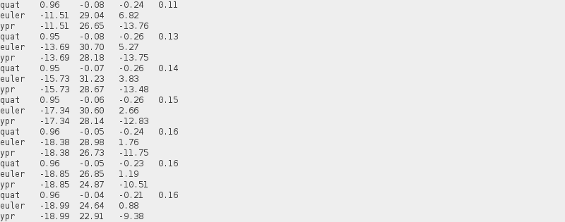
The screenshots below show a sample of the different angle output options, from the MPU6050, observed in the Arduino IDE serial monitor.

MPU6050 Offsets and Calibration
Sensors are used to measure various physical quantities. As stated earlier, the MPU6050 sensor measures angular velocity and acceleration of an object or system it's mounted on or housed in. Ideally sensors are precise, produce the same output from the same input, and able to reliably detect minor changes in the measured parameter. However, in the real world sensors aren't perfect. Even sensors produced by the same manufacturer aren't guaranteed to function uniformly; sensor tolerances, made available in datasheets by manufacturers, reflect this potential variation.
Placing an MPU6050 board still and horizontally flat, then reading the raw angular velocity and acceleration values will most likely output nonzero values instead of zeros as one might expect. These variations are called sensor noise and can be due to a multitude of factors. Nonetheless, it's much easier to filter out the noise by calibrating the sensor rather than correct each of these factors.
The observed nonzero values are known as the sensor offsets. But before filtering out these offsets, they need to be scaled appropriately to the desired sensor sensitivity. The subsequent subsection details the process of calculating the sensor offsets while accounting for this sensitivity.
Calculating MPU6050 offsets
The steps for calculating the MPU6050 board offsets were mainly obtained from the forum post here and modified for this project. The two main steps needed to calculate the offsets are as follows,
-
Connect the MPU6050 to an Arduino and place it on a flat and horizontal surface; an inclinometer can be used to check that the sensor is as horizontal as possible. In this project case, the headers that the MPU6050 board is connected to should be checked to ensure a horizontal position for the board.
-
Secondly, upload the
mpu6050_offsets.inosketch, available in this project directory, to the Arduino. Thempu6050_offsets.inosketch is a modification ofMPU6050_raw.inoexample file from the MPU6050 library used to generate offsets.
The mpu6050_offsets.ino sketch is well documented and only the significant parts of the code will be considered to demonstrate the sensor offsets calculation.
- Firstly, all gyroscope and accelerometer offsets are set to 0. This is done inside the
setoffsetValues()function where thecalculatedOffset[]array contains zero elements before calculations are made.
// Set sensor offset values to those of the calculatedOffset array.
accelgyro.setXAccelOffset(calculatedOffset[0]);
accelgyro.setYAccelOffset(calculatedOffset[1]);
accelgyro.setZAccelOffset(calculatedOffset[2]);
accelgyro.setXGyroOffset(calculatedOffset[3]);
accelgyro.setYGyroOffset(calculatedOffset[4]);
accelgyro.setZGyroOffset(calculatedOffset[5]);
- Then the
calculateOffsets()function is recursively called until 30 raw readings of the gyroscope and accelerometer are added up.
// Read raw accel/gyro measurements from device
accelgyro.getMotion6(&rawValue[0], &rawValue[1], &rawValue[2], &rawValue[3], &rawValue[4], &rawValue[5]);

// Sum raw sensor values over 30 readings
// 30 was chosen so that the total obtained is in the short int (int16_t) range.
if(counter < 30){
  for(int i = 0; i<6; i++){
    totalRawValue[i] = totalRawValue[i] + rawValue[i];
    }
    counter ++;
    return calculateOffsets();
}
-
The number 30 was chosen so that the total obtained falls in the short int (
int16_t) range: -32,768 to 32,767.int16_tis the data type used in theMPU6050.cppfile, of the MPU6050 library, for the offset function arguments, likevoid MPU6050_Base::setXGyroOffset(int16_t offset){}for example, and was chosen here for compatibility. Additionally, thegetMotion6()function, used to read the raw sensor measurements, hasint16_tas the data type of its arguments. -
The average values of the total raw readings after 30 readings. Next the offsets were computed as follows,
// Calculate offsets for each sensor axis: ax, ay, az, gx, gy, gz respectively.
calculatedOffset[1] = -averageRawValue[0] / 8;
calculatedOffset[0] = -averageRawValue[1] / 8;
calculatedOffset[2] = (16384 - averageRawValue[2])/ 8;
calculatedOffset[3] = -averageRawValue[3] / 4;
calculatedOffset[4] = -averageRawValue[4] / 4;
calculatedOffset[5] = -averageRawValue[5] / 4;
The above expressions were obtained from this forum post. There, it can be seen that the MPU6050 board is initialized at its most sensitive setting of ±250dps and ±2G for the gyroscope and accelerometer respectively -- this can be confirmed by looking at void MPU6050_Base::initialize() in MPU6050.cpp. In this mode, all gyroscope readings, x and y acceleromter readings are expected to be 0 while the z accelerometer is supposed to measure 1G (g-force) due to acceleration by gravity; which equates to +16384 according to page 29 of the MPU6050 register map and descriptions document. Furthermore, at this setting, the MPU6050 can only read a maximum of ±2G. So with an expected value of +16384, multiplying this by 2 equals 32768 which justifies the short int data type.
But apparently the MPU6050 registers expect settings of ±1000dps and ±16G instead. Therefore the gyroscope and accelerometer sensitivity settings are scaled as 1000dps/4 to 250dps and 16G/8 to 2G respectively.
- The
isOffsetCalculatedboolean flag is set totrueand the calculated offsets are printed out to the serial monitor. The screenshot below shows the output of running the offsets sketch,

-
While ensuring that the MPU6050 is flat and still, the offsets sketch is run multiple times until the outputted offsets settle around an acceptable range. For instance, ±5 for each of the calculated gyroscope offsets and ±100 for the calculated accelerometer offsets.
-
Once this is achieved, write down the offset values as these will be used in the
arduino_gimbal.inofile for calibration purposes.
This offsets generating procedure has to be repeated for every new MPU6050 sensor to be used.
MPU6050 Calibration
The main project sketch, arduino_gimbal.ino, is uploaded to the Arduino to calibrate the MPU6050. The offsets obtained from mpu6050_offsets.ino are passed into the following functions in arduino_gimbal.ino, as shown below,
// Set device offsets obtained from mpu6050_offsets.ino sketch
accelgyro.setXGyroOffset(-199);
accelgyro.setYGyroOffset(-97);
accelgyro.setZGyroOffset(-49);
accelgyro.setZAccelOffset(1914);
This arduino_gimbal.ino adapts the sketch by Make It Smart and sample code in MPU6050_DMP6.ino which only sets the Z-axis accelerometer offset and the gyroscope offsets and is suitable for the objectives of this project.
The MPU6050 is calibrated with inbuilt functions to filter out these offsets in the following code block,
// Calibrate and fine tune MPU6050 with the offsets set above
accelgyro.CalibrateAccel(6);
accelgyro.CalibrateGyro(6);
At the time of this writeup, the functions CalibrateGyro() and CalibrateAccel() both employ a Proportional Integral Derivative (PID) controller for calibration. This can be confirmed in MPU6050.cpp.
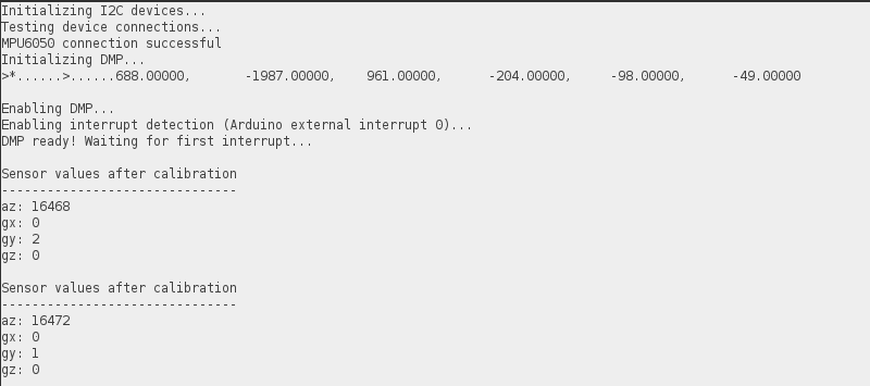
With the MPU6050 board calibrated, outputting the raw sensor values should return close to 0 for each gyroscope axis and +16384 for the z accelerometer (as explained in the previous subsection). The screenshot below shows the calibrated sensor values. Tolerances of ±5 for the gyroscope values and ±100 for the z accelerometer were deemed suitable for this project.
With the gimbal fully assembled and the MPU6050 calibrated, it's time to explain how all the components work together followed by the project demonstration.
Project Working Principle
In summary, the main goal of this project is to stabilize a 3D printed gimbal platform by using an MPU6050 IMU sensor and 3 servo motors connected to an Arduino Nano. The gimbal has been assembled, the MPU6050 board calibrated, what remains is to illustrate how all these components work together to achieve the project's objective.
Firstly, it's ensured that the fitted servo motors are correctly connected to the gimbal. After running the arduino_gimbal.ino to calibrate the MPU6050 board using offsets obtained from mpu6050_offsets.ino, it was noticed that plastic gear of the servo motors were positioned at angles that skewed the gimbal platform off horizontally. Disconnecting the USB cable to power the gimbal off the 9V battery, to fix this misalignment, the plastic gears were unscrewed and adjusted until the platform was horizontally flat and facing the direction (shown in the image below), then fastened again.
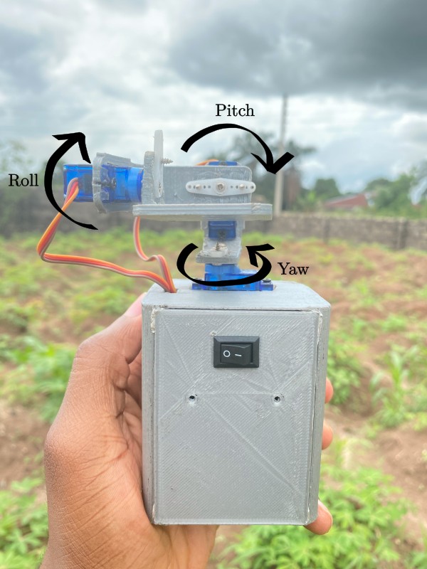
This is the expected position of the gimbal when it's powered on and stationary. The axis of rotation of the servo motors are also labelled in the image above.
As stated earlier, arduino_gimbal.ino is the main sketch for this project. It's well documented therefore, the high level flow chart below will be employed in describing how the project works.
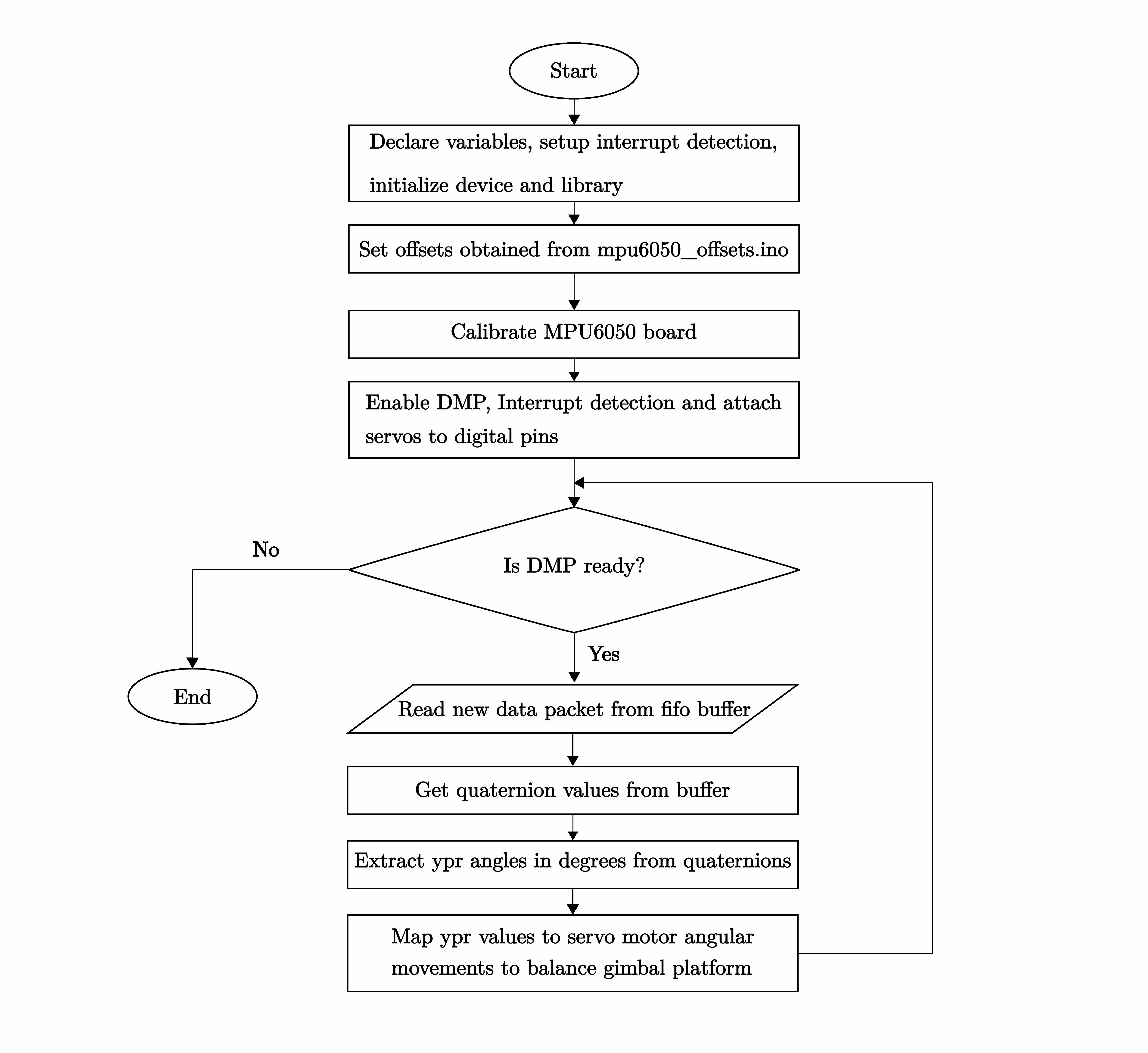
The sketch starts out by declaring required variables, setting up the interrupt detection needed to notify the MPU6050 sensor when new data is available, and initializing the device, the Wire library and serial communication. After a connection has been established with the device, the board is calibrated with offsets obtained from mpu6050_offsets.ino.
Next, the DMP is enabled. Recall that the DMP maintains an internal FIFO buffer which contains quaternion, gyroscope and accelerometer data. Then the interrupt is enabled and the servo motors are attached to respective digital pins. Afterward, the status of the DMP is checked to confirm if it's ready to be used in the main loop; if it isn't, the sketch is stopped.
Once the DMP is confirmed to be available, new data packet from the FIFO buffer is read in. From this packet, quaternion values are obtained and from the quaternion values, ypr angles are calculated. The servo motors require angles in degrees, thus, the ypr values are converted to degrees from radians. These steps are executed in the following block of code,
// Obtain quaternion values from buffer
accelgyro.dmpGetQuaternion(&q, fifoBuffer);
accelgyro.dmpGetGravity(&gravity, &q);

// Convert quaternion to ypr angles
accelgyro.dmpGetYawPitchRoll(ypr, &q, &gravity);

// Convert Yaw, Pitch and Roll values from radians to degrees
ypr[0] = ypr[0] * 180 / M_PI;
ypr[1] = ypr[1] * 180 / M_PI;
ypr[2] = ypr[2] * 180 / M_PI;
Finally, these ypr values are mapped to the servo movements to stabilize the gimbal platform. The mapping is done in such a way that the servo motors move in the opposite direction to the orientation calculated by the MPU6050 board. For instance, if the gimbal is held and tilted towards the left, the mapped angles written to the pitch servo motor produces rotation to the right to counteract this tilt and keep the gimbal platform horizontal.
The three servo motors work in concert in a similar manner to balance the gimbal platform. The pitch and roll servo motors are mapped - 90 to 90 degrees to 180 to 0 degrees while the yaw servo motor is mapped to 0 to 180 degrees. If the servo motor moves in the same direction the gimbal is moved, the erring servo motor will need to have these mappings reversed. The mappings are shown in the block of code below,
/* Map the MPU6050 movement to the angular movements of the servo motors: -90 to 90 degrees from the MPU6050 to
* 0 to 180 for the servos.
*
* This mapping has to be done for the servos to move in the opposite direction of the MPU6050 orientation,
* for each respective axis, to attempt stabilizing the gimbal platform.
*/

int yawValue = map(ypr[0], -90, 90, 0, 180);
int pitchValue = map(ypr[1], -90, 90, 180, 0);
int rollValue = map(ypr[2], -90, 90, 180, 0);

// Control servos according to the MPU6050 orientation
servoYaw.write(yawValue);
servoPitch.write(pitchValue);
servoRoll.write(rollValue);
The loop starts again by checking if the DMP is ready to be used and the subsequent steps outlined earlier are executed. This process continues until the switch is flipped to turn off the gimbal.
Project Demonstration
The following video walks through the setup procedure for this project.
Recommendations
The main recommendations relate to ways to improve assembling the project. These include:
- Using a smaller buck or voltage regulator. The buck regulator used here barely fit into the gimbal body for the electronic components.
- Using a smaller battery, like a Lithium Ion Polymer (Lipo) battery, to reduce the space occupied by the battery in the body.
Another suggestion would be to explore connecting the external battery power (within a range of 7-12V) directly to the Vin pin of the Arduino Nano, thus relying on the internal 5V regulator instead. If feasible, this eliminates the need for an external buck regulator thereby making the gimbal body more spacious.
